
Path planning to control robotic arm for suturing
Published:
Project for CS-6739 Medical robotics course, MSCS Gatech, USA
Team members: Amritpal Singh, Oluwatofunmi M Sodimu Group 5 (G) , BMED 6739 Medical robotics Advisor - Prof. Yue Chen
Project type: Application project
Demo

Abstract
In this work, we perform path planning and end effector modifications for a 5 DOF xARM robot. We calculate the forward kinematics and jacobian for the robot and implement resolved rates for path planning. We transfer these results on to the real robot using arduino. We provide links to our code for matlab simulations and final demo videos.
Introduction
Suturing is a medical procedure that involves the use of a sterile needle and thread to close up a wound/incision in/on the body. When performed manually, this procedure is often tedious, unsafe due to the possibility of a needle stick injury, and its accuracy depends on the dexterity of the practitioner. Manual suturing is also difficult to implement in minimally-invasive procedures (e.g. a keyhole surgery) due to the limited workspace. Thus, the automation of the suturing process would not only increase its speed and accuracy, but simplify and expand its use in minimally-invasive procedures.
Much research has already been done on the automation of suturing through the use of Robotic Surgical Assistants (RSAs) [1]-[4], which are surgeon-controlled robots that may have an attended, unattended, or hybrid robotic process automation. Therefore, many commercial RSA’s for suturing already exist, e.g., the da Vinci surgical system. This system is commonly used for minimally-invasive surgeries e.g. laparoscopic surgeries, and is equipped with vision and instruments that can be controlled by the surgeon to make incisions, perform suturing and other procedures.
Inspired by the da Vinci system, we set out to demonstrate automated suturing with an already existing robotic arm. The scope of the project included:
- Purchase and assembly of robotic arm
- Modification of end-effector to enable it grip and insert needle
- Determination of the forward kinematics of the arm
- Implementation of resolved rates code in MATLAB for path planning
- Establishment of communication between the robotic arm MATLAB, and Arduino for ease of control
- Development of a tissue replica to demonstrate suturing
Methods and Results
Robot description
The 5 degrees of freedom (DOF) + gripper robotic arm was purchased from a company called Lewansoul. The arm has a maximum vertical and horizontal span of 42.6cm and 36.1cm respectively, and it is theoretically capable of lifting objects that weigh up to 500g (at least 10 times greater than the mass of a needle). The bus servos used are equipped with a feedback function that provides information on the current joint variables, enabling us to easily verify our forward kinematics.
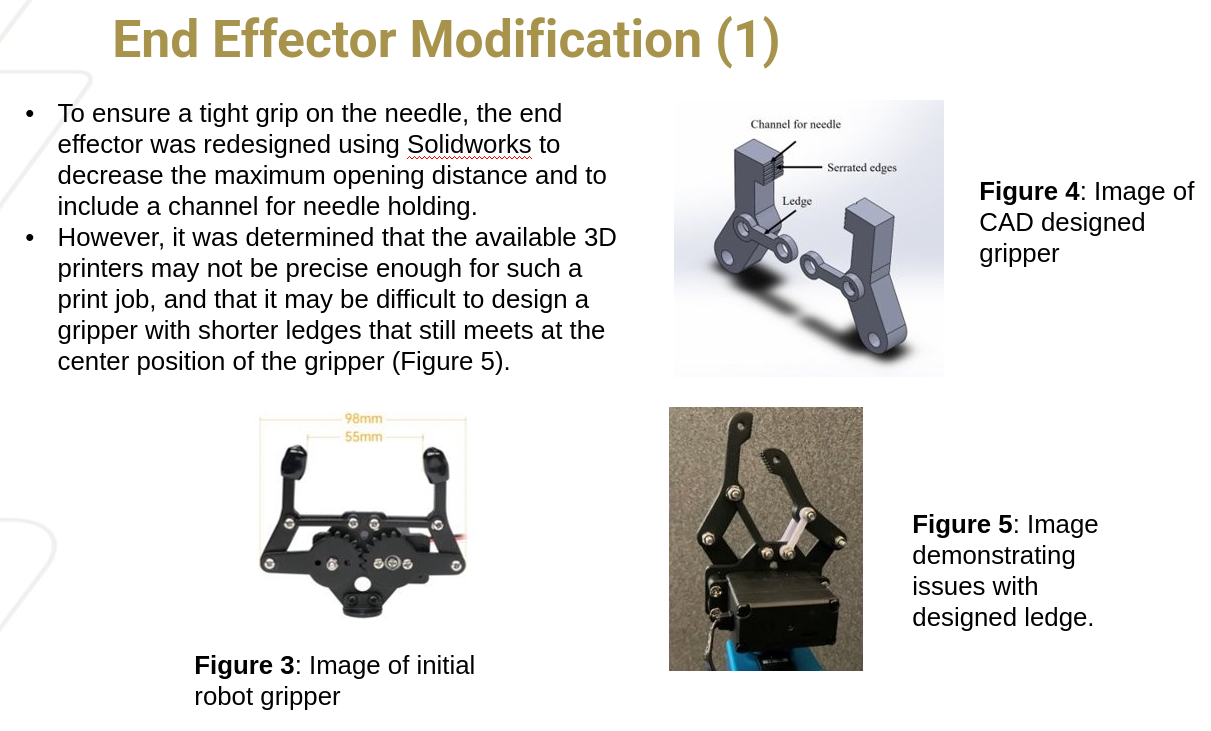
Modification of end-effector
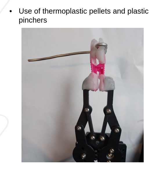
To enable a stronger grip on the needle, we redesigned the end-effector to include a channel for needle placement, serrated teeth to lock the needle in place, and a shorter ledge to decrease the maximum opening distance of the gripper (\textbf{Figure 2}). The new ledges were manufactured by laser cutting and the claws were to be manufactured by 3D printing. Upon testing out the new ledges, we realized that we might need to iterate through different ledge lengths or further modify the claws for them to meet at the center position. It was also determined that it might be difficult to 3D print the modified claws due to the resolution of the available printers being slightly larger than the width of the teeth. Thus, we decided to use thermoplastic pellets and plastic tweezers to modify the ends of the end-effector instead of the original idea.
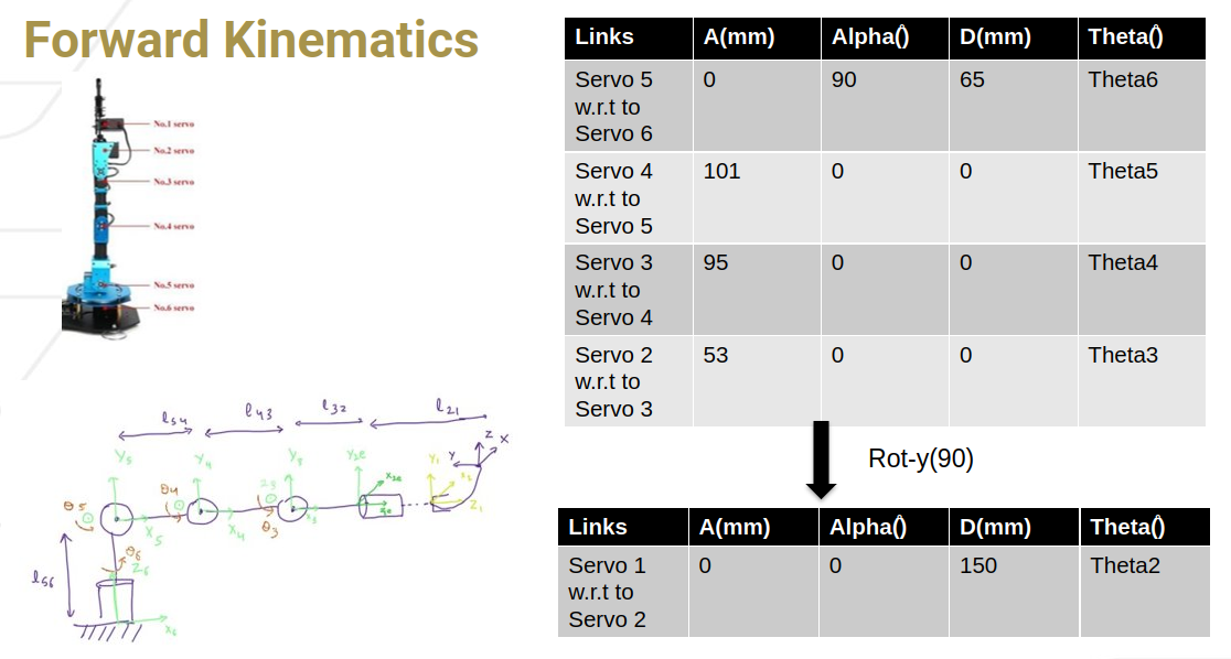
Forward Kinematics
The DH approach was used to derive the forward kinematics of the robotic arm. However, due to the disconnection between the axes of the second and third servos, a homogeneous transformation (rotation about the y axis) was used to transform the expected axes of servo 2 to the actual axes, before deriving the remaining DH parameters.
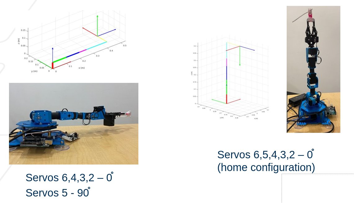
We used MATLAB to verify the forward kinematics of the robotic arm by trying out different configurations, such as the home configuration i.e. all servo angles at 0 degrees, and the vertical configuration i.e. servos 1,2,3,4,6 at 0 degrees and servo 5 at 90 degrees.
Workspace of Robot
Path Planning
Resolved rates
The pseudo code for resolved rates algorithm with position and orientation error control. For our robot, we use both position and orientation control. For our current implementation, we set certain parameters. For orientation, we set termination at 0.02 and brake point at 0.5, and for position we set termination at 0.003 and brake point at 0.03. Linear velocity was capped between 0.15 and 0.07, while angular velocity was capped between 0.7 and 0.14. 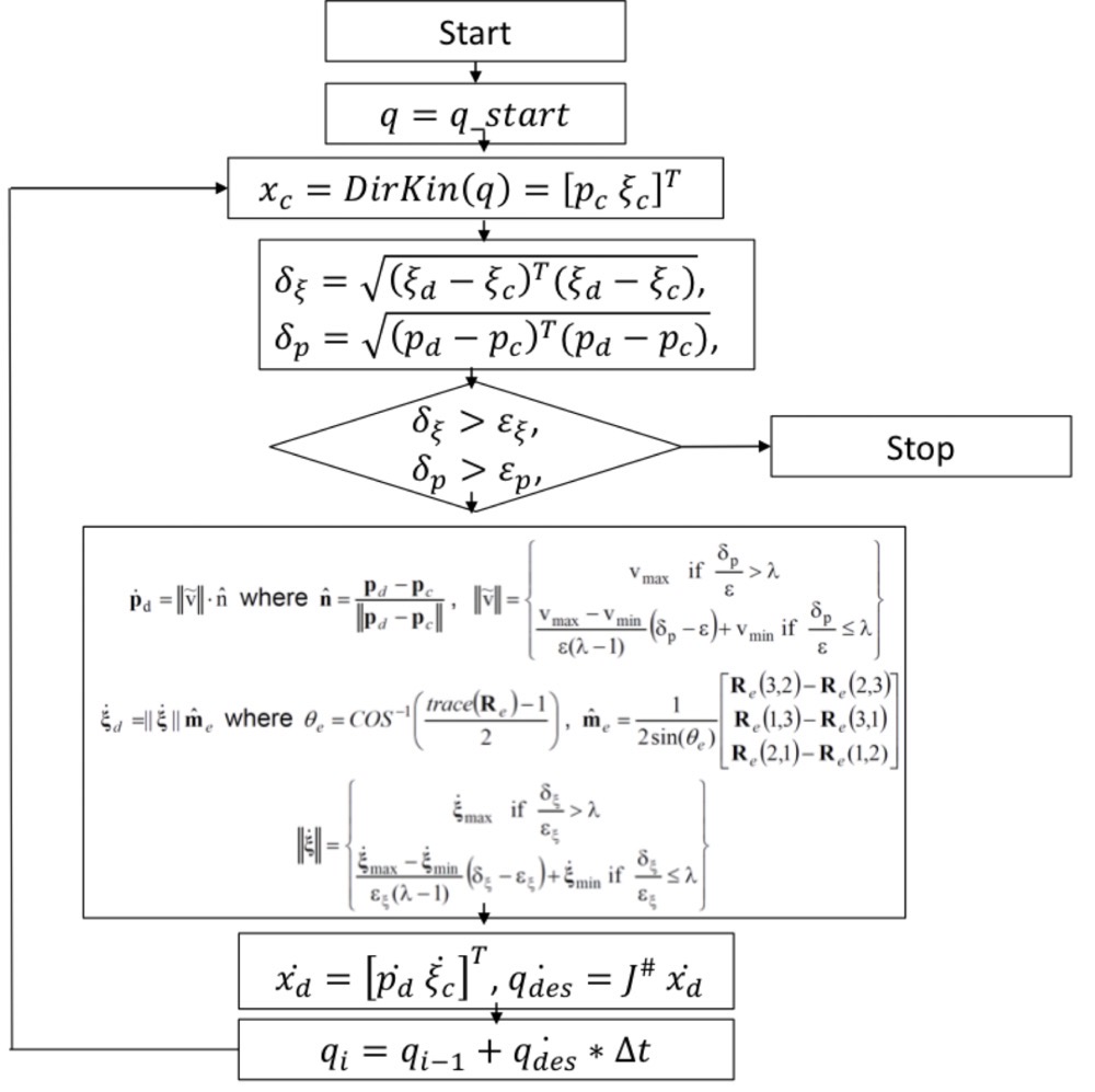
Path planning for the straight needle:
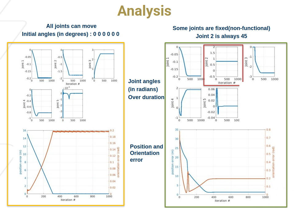
For straight needles, we modified the forward kinematics of the robotic arm, such that the needle is perpendicular to the end effector, allowing direct insertion into the entry points. We monitor all the angles along with position and orientation errors during different time steps and plot them. As seen in Figure \ref{fig:normal_case_error}, the resolved rates allow us to linearly reduce the position error. The orientation error does increase during this process, while still staying less than the given threshold. Figure \ref{fig:normal_case_angles} shows the transition of different angles during this process. The robot gets stuck in some orientations, leading to bumpy transitions at times. This is likely due to the high-velocity values allowed. 
Path planning under constrained angles:
There can be scenarios where one of the robot’s joints stops working. In our case, joint 5 stopped working due to controller issues. So, we developed a resolved rates control where one of the angles is constantly fixed. In the given example, we fix the angle to 45 degrees. We were still able to reduce the position and orientation errors to given thresholds as shown.
Random initizalisation
Start from random angles 
Analysis
Establishing communication between the Robotic arm, MATLAB, and Arduino
An Arduino Uno was connected to the micro controller of the robotic arm through its serial port to enable us control the movements of the arm and receive feedback on the joint variables. The resolved rates code was used to generate an array of joint variables for each servo to reach the needle entry point. This array was converted from a scale of -90 to 90 degrees to 0 - 1000, as is the manufacturers convention, and then added to the Arduino code. The subsequent curved motion of the needle to enter and exit the entry point/hole was hard-coded.
Building Tissue setup
We built the demo tissue for this experiment using a piece of sponge. A horizontal line in the center was made, as the incision line. Two points - entry and exit were made at equal distances from the center and connected underneath using a C-shaped piece of straw. The plan was to insert the needle from the entry point, exit through the exit point, and then continue to next entry point, moving left to right. Due to the inaccuracy of the robotic arm, we decided to simplify our tissue to accommodate it.
Conclusion and Future Work
In this work, we demonstrated the use of an already existing 5 DOF + gripper robotic arm to perform the task of suturing. However, this demonstration is limited by its use of one robotic arm, which prevented the needle hand off and completion of a suture/stitch. It is also limited by the lack of vision which restricted us to the use of fixed entry points for our demonstration. In future versions of this system, we seek to incorporate:
- accounting for different orientations of needle insertion
- a second arm to pull the needle from the other end
- and computer vision for image-based needle incision.
References:
S. Sen, A. Garg, D. V. Gealy, S. McKinley, Y. Jen and K. Goldberg, “Automating multi-throw multilateral surgical suturing with a mechanical needle guide and sequential convex optimization,” 2016 IEEE International Conference on Robotics and Automation (ICRA), 2016, pp. 4178-4185, doi: 10.1109/ICRA.2016.7487611.
H. Kang and J. T. Wen, “Autonomous suturing using minimally invasive surgical robots,” in Control Applications, 2000. Proceedings of the 2000 IEEE International Conference on. IEEE, 2000, pp.742–747.
C. Staub, T. Osa, A. Knoll, and R. Bauernschmitt, “Automation of tissue piercing using circular needles and vision guidance for computer aided laparoscopic surgery,” in Robotics and Automation (ICRA), 2010 IEEE International Conference on, 2010.
J. van den Berg, S. Miller, D. Duckworth, H. Hu, A. Wan, X.-Y. Fu, K. Goldberg, and P. Abbeel, “Superhuman performance of surgical tasks by robots using iterative learning from human-guided demonstrations,” Robotics and Automation (ICRA), 2011 IEEE International Conference on, 2010.
A. P. Stegemann, K. Ahmed, J. R. Syed, S. Rehman, K. Ghani, R. Autorino, M. Sharif, A. Rao, Y. Shi, G. E. Wilding, et al., “Fundamental skills of robotic surgery: a multi-institutional randomized controlled trial for validation of a simulation-based curriculum,” Urology, 2013.